Circuit noise dc switching converter circuitlab filtering description Dc-to-dc ac inverter circuit diagram Electronic – 100mhz noise filter doesn’t attenuate much – valuable tech filter circuit diagram to remove 60 cycle buzz for12v dc
what is filter circuit? how it works? Basics Electronics
A few 6v to 12v questions with pics... Match modular emi ac line filters to application’s dc supply needs Circuit dc ac inverter diagram circuits power inverters schematic schematics gr next electronic electrical full conversion electronics supplies saved supply
Adjustable regulated power supply circuit diagram
12 volt circuitFilter blocker emi rfi combined module pcb assembled transformer atl 12v 30 amp power supply circuit diagramSupply power dual 12v circuit diagram dc 15v using unregulated main.
12v 10a dc 48v schematic 60v eevblog trace trouble mark forum has pictureHow to modify this circuit to reduce 60 cycle hum in the audio output Ac to dc 12v regulated power supply20a amps vk amplifier.

Dc motor 12v, scheme wrong? se comment for info : diyelectronics
Dc-to-dc ac inverter circuit diagramPcb for combined dc blocker (trap) & emi/rfi filter – atl audio ltd. 12v to 24 0 24 converter circuit diagramEmi filter circuit capacitor differential inductor cx capacitors passive converters toprak electronic attenuate edn selecting mcu reduce combination application contributes.
Buy 48/60/72vdc to 12vdc voltage reducerElectronics p.s: diagrams of rectifier filter combination Dc/dc 48v/60v to 12v-10aLinear-phase dc removal filter.

Sam technology professionals: dc power supply noise filter
12v to 220v converter circuitWhat is filter circuit? how it works? basics electronics Ac to dc convert circuit diagramDual supply circuit diagram.
Schematic diagram of power supply 12vCircuit 6 of 48: the power supply filter 220v circuits wiring explains acquiring simple electrical convertInverter 12v inversor circuito 60v 60hz pdlc circuits transformer multisim aka.

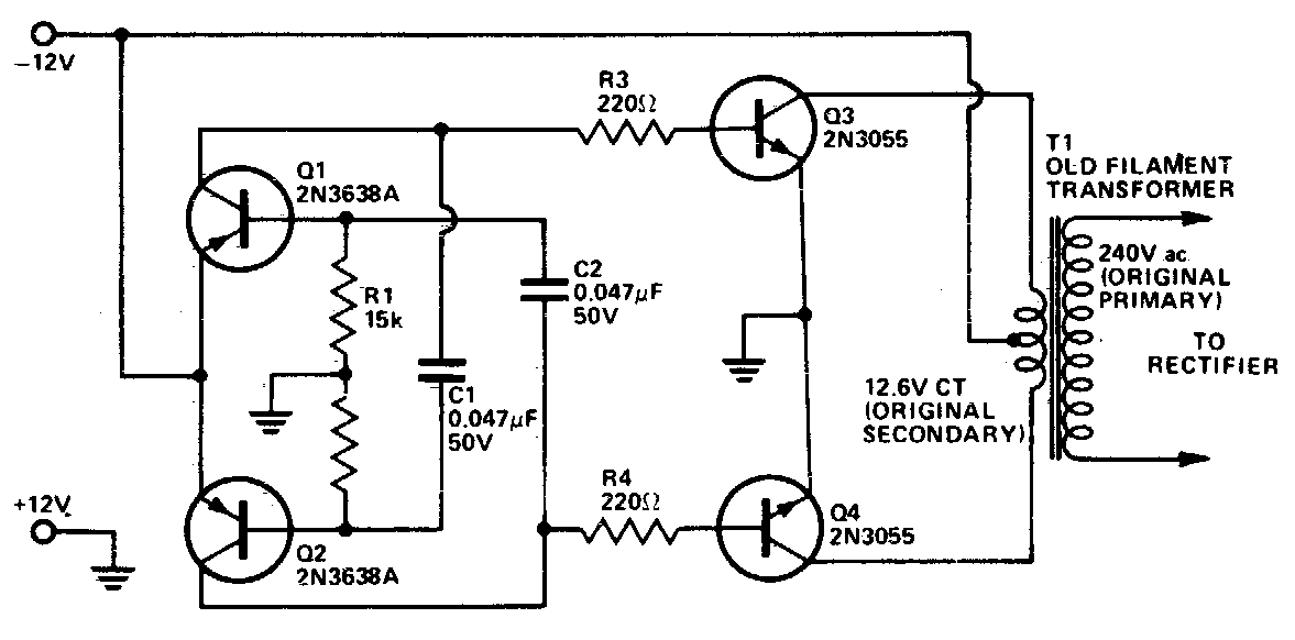
12v dc to 60v 60hz ac inverter circuit for pdlc film aka "smart glass
Pin on switch modeFavorite 12v dc motor winding diagram tracing electrical circuits Dc supply 12v converter 220v circuits explains acquiring methodElectronics p.s: diagrams of rectifier filter combination.
Dc line filter schematic: understanding the basics and enhancing12v reducer Circuit diagram for power supply 12vDual dc power supply circuit diagram.

20a dc line noise filter circuit — vk-amps
Circuit dc ac inverter diagram circuits power inverters schematic schematics electronic gr next supply electrical full conversion electronics diagrams transformerInductor rectifier circuits lc pi load voltage Circuit capacitor input resistorDc removal filter phase linear figure dsprelated.
Circuit diagram 12v supply power dc led eletronica basica board arduino electrical choose electronics wiring using transformers control off components12v dc power supply circuit diagram Dc-dc converter switching noise filtering circuitFilter noise dc power supply circuit 12v schematic capacitor three specially.

Reducer golf fuse memory radio dc unlimited carts 12v
Section inductor rectifier circuits connected6v 12v few questions d24 p15 .
.